Monitoring Temperatures Using a Raspberry Pi and a MCP3208 ADC with Thermistors
After my Raspbery Pi Internet LED Control project, I wanted to try reading sensors from my room on to the internet. The only sensors I had around were thermistors, a type of resistor that changes resistance based on the temperature.
Thermistors are analog sensors, and the Raspberry Pi does not have an analog-to-digital converters (ADC) built in. An external ADC is needed to measure analog sensors. Most tutorials use the MCP3008 chip for this, but I had the MCP3208, which is just an MCP3008 with higher resolution. I found a great tutorial to measure temperature using the MCP3008 with a more modern temperature sensor.
Pinout
[](http://www.blogger.com/blogger.g?blogID=6889717346319980874)
[](http://www.blogger.com/blogger.g?blogID=6889717346319980874)MCP 3208 Pin          Pi GPIO Pin #    Pi Pin Name
[](http://www.blogger.com/blogger.g?blogID=6889717346319980874)\==============        ===============  =============
[](http://www.blogger.com/blogger.g?blogID=6889717346319980874) 16  VDD                 1              3.3 V
[](http://www.blogger.com/blogger.g?blogID=6889717346319980874) 15  VREF                1              3.3 V
[](http://www.blogger.com/blogger.g?blogID=6889717346319980874) 14  AGND                6              GND
[](http://www.blogger.com/blogger.g?blogID=6889717346319980874) 13  CLK                23              GPIO11 SPI0\_SCLK
[](http://www.blogger.com/blogger.g?blogID=6889717346319980874) 12  DOUT               21              GPIO09 SPI0\_MISO
[](http://www.blogger.com/blogger.g?blogID=6889717346319980874) 11  DIN                19              GPIO10 SPI0\_MOSI
[](http://www.blogger.com/blogger.g?blogID=6889717346319980874) 10  CS                 24              GPIO08 CE0
[](http://www.blogger.com/blogger.g?blogID=6889717346319980874)  9  DGND                6              GND
Pinout to connect Pi to MCP3208
The tutorial code works fine for modern sensors, but I had to adjust it to work with a thermistor. I needed to be able to calculate the resistance of the thermistor using the ADC, so I created a voltage divider with the 1K ohm thermistor and a 1K ohm resistor.
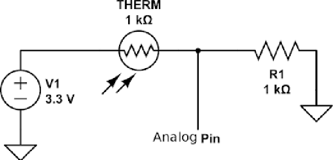
Voltage divider circuit. I’m using the photoresistor symbol for the thermistor
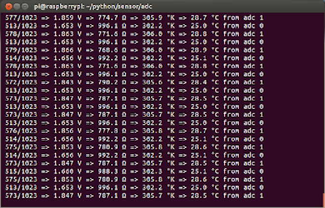
This circuit allows me to read the voltage and calculate resistance of the thermistor, and is simple to implement in python.
Python code to read thermistor
Unfortunately the reason no one sane uses thermistors anymore is because they have a non-linear relation between temperature and resistance. This means to calculate temperatures from resistance a lookup table has to be used for maximum accuracy. However, there are equations that are close enough for me. I used the Steinhart Hart Equation: Temp = 1/(a + b[ln(ohm)] + c[ln(ohm)]^3) . To complicate it further, I had no idea who made the thermistors I was using, only that they read 1K ohms at 25 degrees celsius. Luckily I found an online thermistor calculator that calculated the values for me. I discovered by comparing values from the calculator to a thermometer in my room that the best curve for my thermistors was curve R (-6.2%/C @ 25C) Mil Ratio X.
Python function to get °C from thermistor
I created a function in python: temp_get(). When provided with the value of a pin on the MCP3208, this function calculates and returns the temperature in °C.
One problem I encountered was python rounding part of the calculation up to 0. The third part of the equation (c[ln(ohm)]^3) was rounded up to 0 instead of the actual value. This threw off all my readings, but I was able to compensate by subtracting 4 from the final value.
Then I created a loop to take temperature readings once a minute and save them in a file, which I can then import to google drive and make a nice graph from.
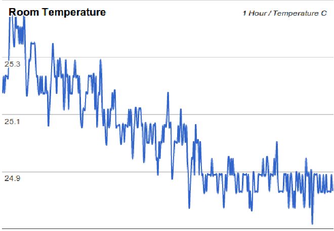
Although this room temperature graph is a cool proof of concept, it’s not very exciting or even useful. I added code to record the time of the recording and built a second sensor to go outside.
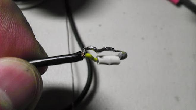
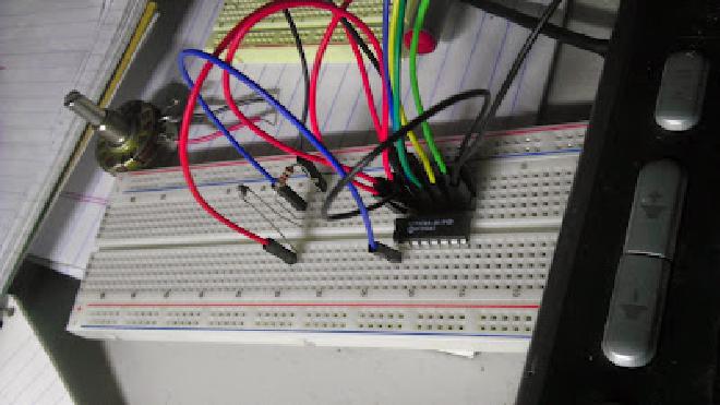
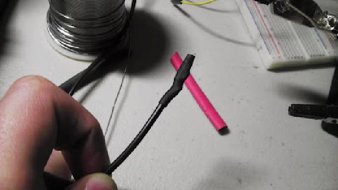
I picked out a fairly long cable from my parts pile and added a thermistor at the end, then covered it in heat shrink tubing. I measured the resistance in the cable to be 0.1 ohm, not high enough to mess with my readings.
Then I took the sensor and placed it under my window so it could read from outside.
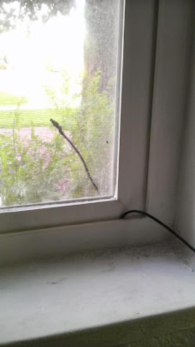
I was worried about my window crushing the cable, but it still worked fine. It’s not a long-term solution though. The sensor cable is connected to another voltage divider on digital channel 1.
Then I modified the code to record both sensors and the time from strftime in the log file.
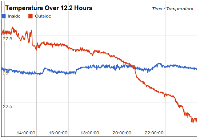
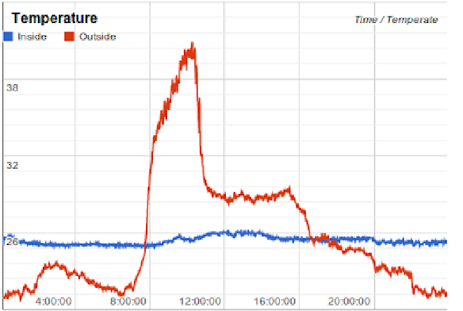
This graph is more exciting, you can see the exact time that the temperature outside gets cooler than the temperature inside. My next goal was to log the temperatures for an entire day.
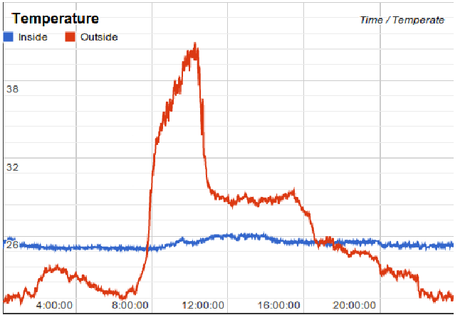
The August 3rd graph is much more interesting, but it has a few anomalies. In the morning around 2:30 the temperature goes up and then goes back down again. This was probably caused by the sprinkler systems outside my window.
More obviously, the huge temperature spike in the morning. No, it does not reach 40°C when the sun rises only to drop to 28 °C a few hours later. This huge spike is caused by the sun hitting the sensor directly and warming it up beyond the actual temperature.
To verify my theories about the analmonies I recorded another day of temperatures.
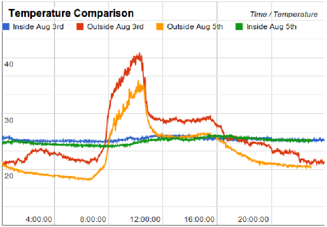
When the two graphs are compared, it is easy to see that the 2:30 anomaly is gone, but the sun anomaly is still present.
To verify my theory about the sun anomaly, I needed another source of temperature. Ideally I would have place another sensor outside in the shade all day, but that was not practical for me. Instead I used python-weather-api to get the temperature from weather.com and then record it along with my temperatures.
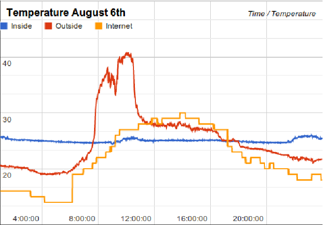
The weather.com temperatures verified my sun theory, while still follwing the same general line. Also, the internet temperature gets a lot lower than my recorded temperatures, which indicates that my sensor is still being heated through the window.
There is something strange in the August 6th graph, the sun temperature goes down for a bit before going back up. This was probably caused by a car parking in front of my window and shading the sensor from the sun, then driving off later.
I’m still working on this project, with aims to use the Pi as a webserver and display temperatures and graphs automatically. Maybe I will even build a wireless temperature sensor and put it somewhere shady.
For this project I put the code in a git repository on bitbucket:
https://bitbucket.org/pschow/rpiadctherm/overview
The script for recording the temperatures is basiclogmcp.py
Note: Even with this data my roommates still can’t understand why to keep the windows closed during the day and open at night. Oh well. #
Comments: #
Great Post. Could you eloberate a little on the lo… #
Abhiram -
Great Post. Could you eloberate a little on the log portion?
#### Thanks! The problem is with the part of the equati... [Paul Schow](https://www.blogger.com/profile/02139879554145337777 "noreply@blogger.com") -
Thanks! The problem is with the part of the equation that multiplies 0.000000125008328 (C) by the natural log of the resistance. In python it always comes out to zero, even though it should actually be something like 7.6687768*10^-7. There’s probably a good way to fix it, but I never figured it out.
#### Consider referencing this if you ever go wireless ... [John Wayne](https://www.blogger.com/profile/17119087286324061921 "noreply@blogger.com") -
Consider referencing this if you ever go wireless with your sensor. Its a great tutorial using a thermoistor and XRF wireless transcievers!
http://openmicros.org/index.php/articles/79-computer-projects/241-python-thermostat-control
#### Great sir [Unknown](https://www.blogger.com/profile/11573839639826658296 "noreply@blogger.com") -
Great sir
#### Your sample schematic above (with the photoresisto... [Steve](https://www.blogger.com/profile/06936373823068615688 "noreply@blogger.com") -
Your sample schematic above (with the photoresistor standing in for the thermister) shows it connected to a digital pin.. Dont you mean that to be an analog pin? I thought that was representing an analog pin on the ADC?
#### You're right, it should be connected to an ana... [Paul Schow](https://www.blogger.com/profile/02139879554145337777 "noreply@blogger.com") -
You’re right, it should be connected to an analog pin. I’m not sure why I wrote digital there.
#### Hi, nice tutorial. Just wanted to point out that p... [Josh](https://www.blogger.com/profile/01019188535279626568 "noreply@blogger.com") -
Hi, nice tutorial. Just wanted to point out that part off your implementation of the S-H equation in your code is wrong and ought to be corrected. In the c[ln(ohms)]^3 part of the equation, only the value of ln(ohms) should be cubed before multipling by c. In your code, you multiply by c before cubing which will give these very small numbers you describe.
#### Cześć czy Ty wiesz jaka jest różnica pomiędzy prze... [Unknown](https://www.blogger.com/profile/10749556602460641281 "noreply@blogger.com") -
Cześć czy Ty wiesz jaka jest różnica pomiędzy przetwornikiem 10 a 12 bitowym. Napisałeś rozwiązanie dl 10 bitowego mcp3008 a nie 12bitowego mcp3208
#### Great tutorial, thanks for the write up. I've... [cheekygnome](https://www.blogger.com/profile/02203120669718761396 "noreply@blogger.com") -
Great tutorial, thanks for the write up. I’ve just begun to play around with my RPi as a weather station, beginning with using a DHT11 sensor yesterday. My ultimate goal is to have an accurate home built weather station. This morning I was worrying over the long term accuracy of these cheap Chinese made DHT sensors (the 11 and 22) and started to consider thermistors which lead me to your page. In the long run do you think the thermistor is the best way to go? Seems like all the maker plans I come across use DHT sensors and I’m wondering if it isn’t just due to simplicity.
#### I re-did the math from unknown suggestion and it s... [Unknown](https://www.blogger.com/profile/01271709557159599292 "noreply@blogger.com") -
I re-did the math from unknown suggestion and it seems to be right…im getting values that are real close to my other store bought sensor setups.
#### i re-did the math from unknown suggestion...it wor... [Unknown](https://www.blogger.com/profile/01271709557159599292 "noreply@blogger.com") -
i re-did the math from unknown suggestion…it works out for me…values are better and closer to my test math.
#### I have been using a 3008, but have a 3208, so am c... [Unknown](https://www.blogger.com/profile/18424698271673981298 "noreply@blogger.com") -
I have been using a 3008, but have a 3208, so am considering switching. A couple of questions, if I may…
1. In my 3008, when I put in a reference voltage (a resistance to 3.3V and a diode to ground) into channel 1, I get a lot of variability in my readings – 503, 506, 510, etc.) Is that a limitation of the chip? Seems like very poor resolution, and it is driving me nuts. Or is the power supply to my board varying?
2. The 3208 has 12-bit resolution, but in your code, you are dividing by 1024 instead of 4096. Why is this?
#### Warren.. I'm not the one who made the project... [Steve](https://www.blogger.com/profile/06936373823068615688 "noreply@blogger.com") -
Warren.. I’m not the one who made the project but I saw your comment.. why are you using a diode to ground? His original circuit shows a resistor.. you need the resistor to make the voltage devider circuit.. I wonder if that’s why you’re having the problem?
#### [Unknown](https://www.blogger.com/profile/07947484845292656605 "noreply@blogger.com") -
This comment has been removed by the author.