$25 Satellite Tracker
After building my QFH antenna, I became more interested in satellite communications. The QFH antenna works great for circularly polarized signals like weather satellites, but something like a yagi or log-periodic antenna is better for most sats, because it can be pointed directly at the sat.
After a short break where I interned at Keysight Technologies then finished my last semester at school, I built a tape measure yagi for 145.8 MHz to receive ISS SSTV broadcasts. It works great for that, but after a few passes I started to wonder if there was a better way. Ideally, some way to track the sat with a computer, automatically. Commercial solutions exist of course, like the Yaesu G-5500. This is a bit expensive for my tastes, and meant for more permanent installations. SatNOGS is a great open-source solution, if you have access to a 3D printer and some parts. I still want to build the SatNOGS rotor, but first I wanted to see if I could build my own version cheaper.
* I’ll tell you straight away that my solution ended up costing more than $25, but I think someone could make the same thing for $25.
Hardware #
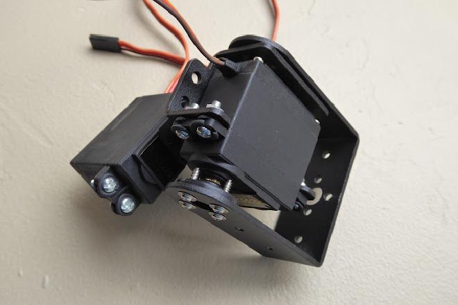
As with most projects these days, I started out by shopping around for parts. Eventually, I found a $25 pan and tilt solution, meant for mounting cameras from drones.
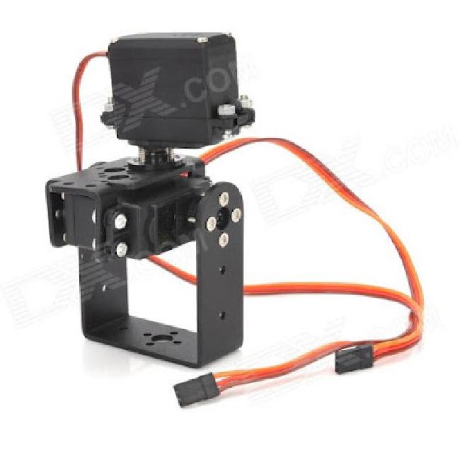
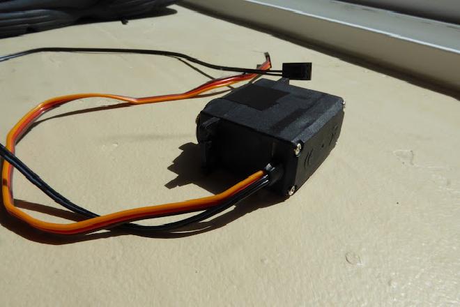
It seemed to me that if I could make the antenna light enough, I should be able to use something like this to point it wherever I want. I ordered one of these, and also some okay servos ($7.21) with metal mounting brackets ($3.74) in case I wanted to completely make my own solution.
Naturally, the servos and brackets shipped about a week earlier than the $25 pan and tilt kit. I couldn’t be bothered to wait, so I got right to trying to make it all fit together.
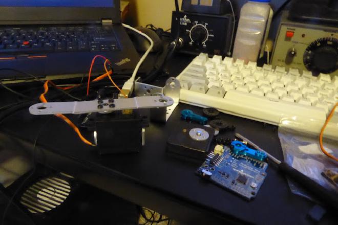
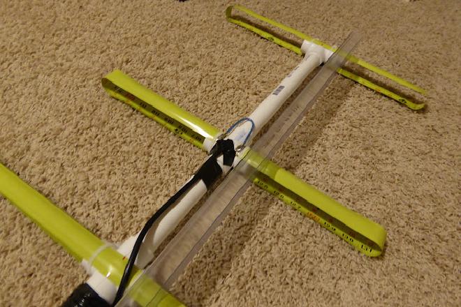
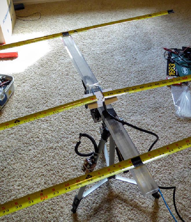
Using a bunch of masking tape and an arduino, I began to test if these servos could even support a pvc tape measure antenna.
The answer: kinda. The azimuth control works fine, but the elevation struggles a lot. The PVC elbows add more weight than you would think, and make it hard to balance. The antenna has to be made of something lighter than PVC (measuring tape is still light enough).
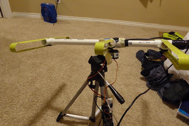
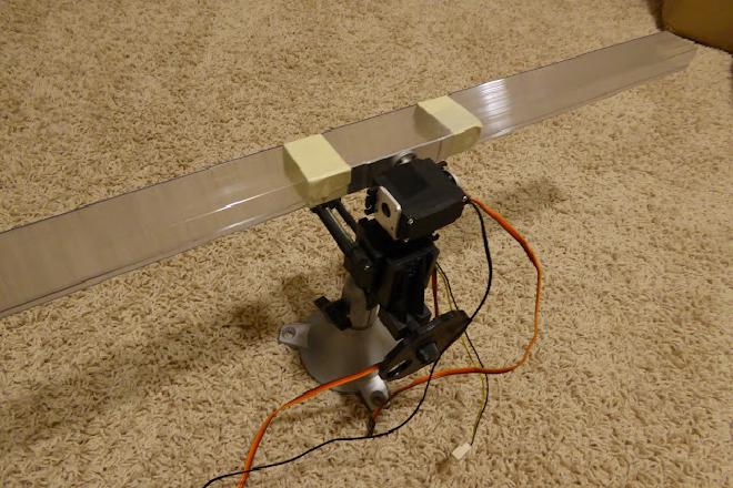
Large antistatic tubes used to ship high-speed connectors in work well for this. They’re long enough, and very lightweight while still being rigid. If I was doing it again though, I would probably just use a cheap yardstick.
The servos have no problems moving an antistatic tube around.
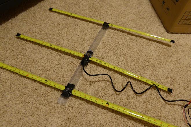
It is a bit harder to attach the measuring tape to a square tube than it is to a pvc elbow. I used very cheap electrical tape for testing, but later actually used screws.
However, after finishing this I took a step back and decided to work on the software more. It’s a bit of a pain to have this huge antenna flailing around when your code has a bug in it.
The arduino servo library is simple enough, and worked well for my servos. I did find that the writeMicroseconds() function worked better for me than the write() function. I made a simple script to control the two servos over the serial terminal: servo_serial.ino.
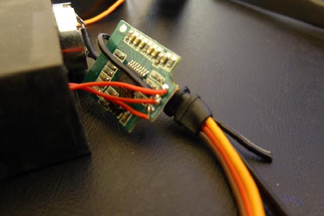
Normally, servos don’t give actual feedback of their position. If you use the read() function, it just returns the last value that was written to the servo. This can be useful in some cases, but I decided I wanted to have actual feedback. The servo uses a potentiometer internally to determine the position, and it’s a simple matter to attach another wire to the center terminal and read the current value using the analog input on the arduino. Credit to jes1510 on trossenrobotics.com for the complete tutorial.
I cut some wires from broken computer fans and got to work.
Now I just hooked the sense wire up to an analog pin on the arduino and read the values. I found my servos typically read between 80 and 445.
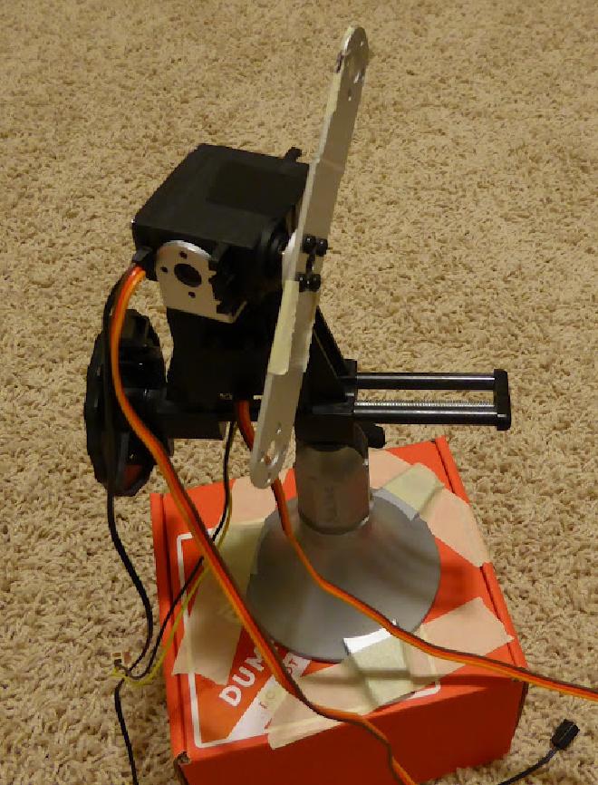
I determined an arrangement for the servos that I thought would be able to track the most satellites (more on this later): azimuth on bottom with elevation on top.
Software #
Computer Side #
Now for the actual satellite tracking. For this, I looked to SatNOGS, which also uses an arduino. Their code interprets serial commands sent using the Easycomm2 protocol, and translates them to stepper or dc motor movements.
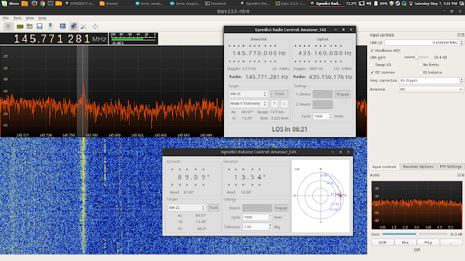
The key here is the Hamlib library for linux. This library includes commands which take output from other programs and use them to control antennas or radios. My favorite satellite tracking program on linux is Gpredict, which works great with Hamlib.
SatNOGS uses the Easycomm2 serial protocol, which Hamlib supports. Then the commands are just sent through the serial port on the arduino and interpreted there.
It’s easy to set up Gpredict with Hamlib, once you understand what’s going on.
First, set up a new rotator interface in Gpredict.
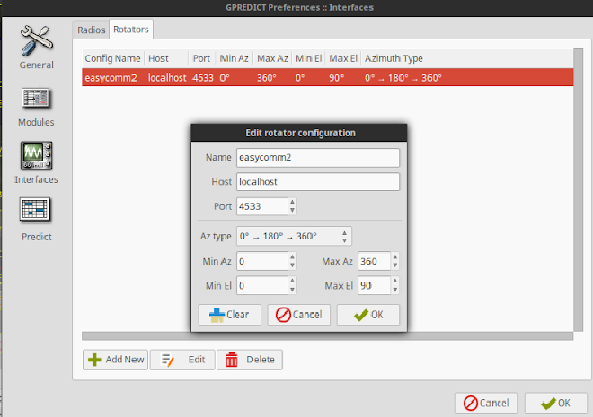
Name can be whatever you want, I chose “easycomm2”. Host is “localhost” unless you are doing this over a network. Port is “4533” by default, but you can change it.
Then, just set up Hamlib to interpret the command.

The command for this is “rotctld” (Hamlib TCP rotator control daemon). Choose the Easycomm2 mode with “-m 202”. The serial baud rate is “-s 19200”, and the serial port for me is “-r /dev/ttyUSB0”.
The full command is “rotctld -m 202 -s 19200 -r /dev/ttyUSB0”. There won’t be any output afterwards unless there is an error.
Next, go to Gpredict and open up the antenna control module.
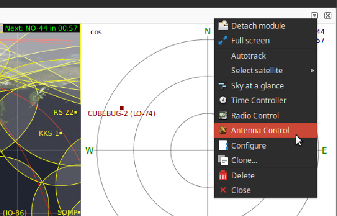
You will get an antenna control panel.
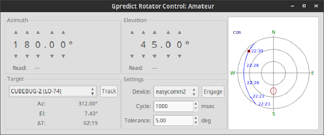
From here you can click “engage” to activate the interface we set up earlier, and then control the antenna any way you want! Select a satellite and then click “track” to track it.
Firmware Side #
Setting up the computer software is the easy part. Luckily people have done a lot of work on this before me, to make it as simple as it is. However, that’s pointless if the hardware doesn’t know how to interpret the commands. The SatNOGS program will interpret the commands correctly and output them so I can use them, but I still wanted to know what was actually being sent. This proved to be more difficult than I first imagined.
I couldn’t just open up the serial monitor on the arduino IDE, because the serial port was already in use. I played around with a bunch of linux serial sniffers and bridges, but couldn’t find one that was extremely simple to set up. Eventually I found the best solution for me was to use a Bus Pirate set to UART monitor.
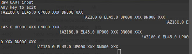
Now that I could see what the Easycomm2 mode was actually putting out, I could better understand it. In my screenshot, I was setting the azimuth to 180 and elevation to 45. Pretty simple.
The SatNOGS stepper_motor_controller.ino already interprets Easycomm2 commands and then translates them into stepper motor controls. The key is the cmd_proc function, which eventually feeds the angles into the deg2step function to calculate the number of steps from degrees, and then feeds that into the stepper_move function. Since the servos don’t need step calculation, I just cut that out and made my own servo_move function. Along with a few other minor changes, I now had the working Servo_easycomm.ino!
At this point it worked! However, I quickly discovered a major problem in my approach, The servos I have only move 180 degrees.

As I figured out, there are 360 degrees in a circle. This means that my tracker can only track a satellite moving through two quadrants of the compass. For the most part it’s not a big deal, just a small inconvenience. Most satellites only move through two quadrants, and a most of those only move through 2 and 3 or 1 and 4.
The solution is to create 4 different programs. One that sets 90 degrees as North and covers from W to E, one that sets 90 degrees to East and covers from North to South, etc. Then, every time I want to track a satellite I just have to load on the correct program and position the tracker so that at 90 degrees it’s pointing in the correct direction.
Of course, Gpredict doesn’t know that there are 4 separate programs. To accommodate this I used the map() function of arduino heavily. This function takes a variable from one range of numbers to another, perfect for what I’m doing.
For example, the program for North, Servo_easycomm_N.ino, has to take inputs from 270 degrees to 90 degrees, and turn them into 0 to 180 degrees for the servo.
<![CDATA[ void servo_move(int stepAz, int stepEl){ int xmape; int xmapr; // map the range of angles to the servo xmape = map(stepEl, 0, 90, 1425, 2400); elservo.writeMicroseconds(xmape); // translate azimuth angles // make 0 degrees pointing north //Serial.println(stepAz); if ((stepAz >= 270) && (stepAz <= 359)){ //quadrant 2 xmapr = map(stepAz, 270, 359, 2300, 1400); roservo.writeMicroseconds(xmapr); } else if((stepAz >= 0) && (stepAz <= 90)){ // quadrant 1 xmapr = map(stepAz, 0, 90, 1400, 500); roservo.writeMicroseconds(xmapr); } } ]]>
Once I figured that out, it was pretty easy.
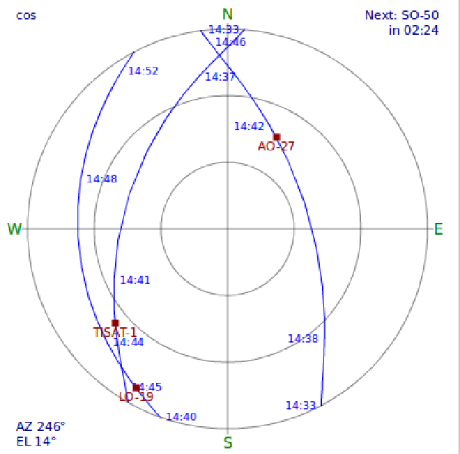
The steps to actually tracking a satellite:
- Open Gpredict and figure out which quadrants the satellite is going through
- Load the correct program into the arduino.
- Wait for the program upload to complete.
- Point the antenna in the correct direction.
- Run “rotctld -m 202 -s 19200 -r /dev/ttyUSB0”
- Open the antenna control in Gpredict.
- Engage the interface.
- Select the satellite.
- Click “Track”
See, simple!
At this point it can actually track satellites:
From a vice on my floor. Not very useful.
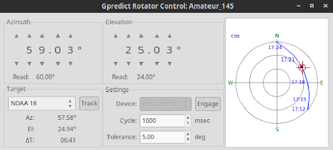
I also implemented the analog feedback into the SatNOGS code. SatNOGS steppers use “step2deg(ELstepper.currentPosition())” to get the current position of their motors in degrees and then print it out where necessary in the code. Gpredict than reads those values and displays the current location of the antenna as a crosshair on the compass.
I just made my own functions to return the elevation or azimuth degrees based on their current analog reading, and then put that in place of the stepper code.
<![CDATA[ int degel(){ int position; int degree; // elevation feedback position = analogRead(elfeedbackPin); // my servo reads 264 at 90 degrees // which is 0 degrees of elevation degree = map(position, 264, 425, 90, 0); return degree; } ]]>
Now Gpredict shows where my antenna is actually pointing!
The other half of the equation is the radio. I used the ever-popular (~$15) RTL-SDR with GQRX as the software. As a satellite moves towards and away from you the frequency changes slightly due to the doppler effect. Luckily, Gpredict can easily interface with GQRX to control the tuning frequency. Gpredict also comes with most satellite frequencies built-in.
Hardware Again #
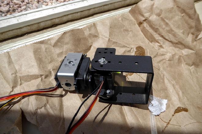
As I was writing the first part of this post, the pan and tilt setup arrived.
Even though I’m pretty sure my setup would have worked, the hardware for the pan and tilt was way better than anything I could have built. The servos are exactly the same, so I switched my modified servos in for the included ones and started using that setup instead. This also required some code tweaking and the elevation control was reversed, but that’s easy.
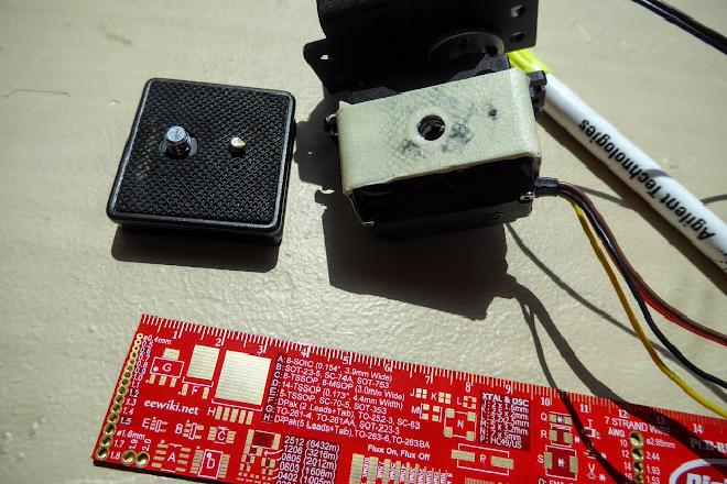
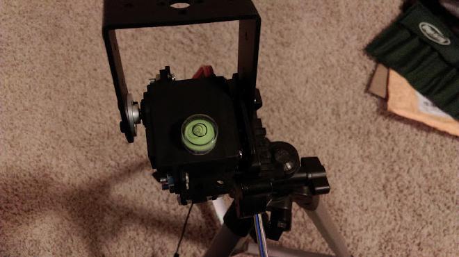
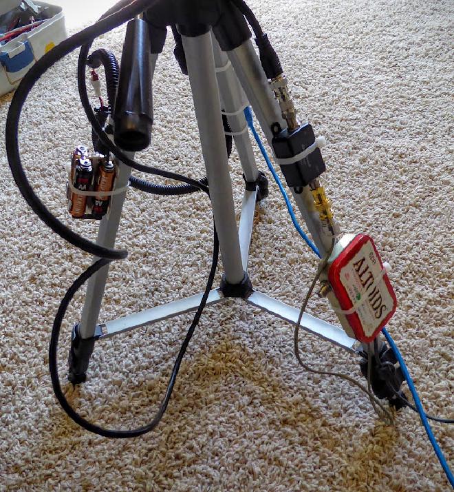
Next I started to consider how I wanted to mount the whole setup to a tripod. The easiest way I could think of was to buy some nuts and epoxy one of them to the side of the azimuth servo. The standard tripod mount is 1/40-20, which can be found at any hardware store in the US.

There’s probably a better way to do this, but it worked well enough. I also drilled a hole in the bracket for the extra pin on the tripod mount, to keep it level.
Going through my junk, I found a circular bubble level which is very helpful when you want to know if something is well… level.
After that it was time to figure out a battery solution. For a couple of days I tried to get one of those external usb power packs working, but it would always shut itself off eventually. I gave up on that for now and bought some AA battery holders. Four AA batteries is more than enough for these servos. In the future I might try a setup with 18650 batteries instead.
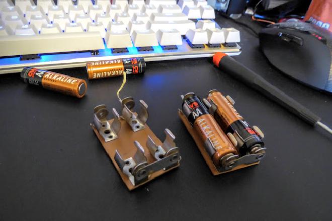
I verified that the 4 AA setup actually works, and then got to wiring everything together. My plan was to cut off all the connectors and replace the servo ones with standard computer power supply connectors, which I have a ton of.
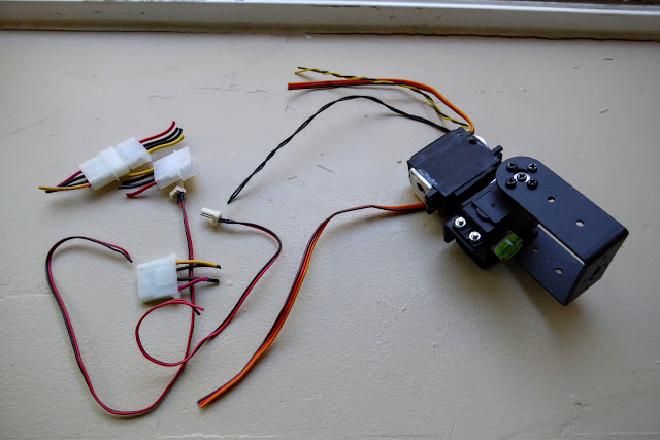
This worked pretty well, and I even used some fan connectors for the arduino and battery connections.
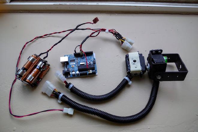
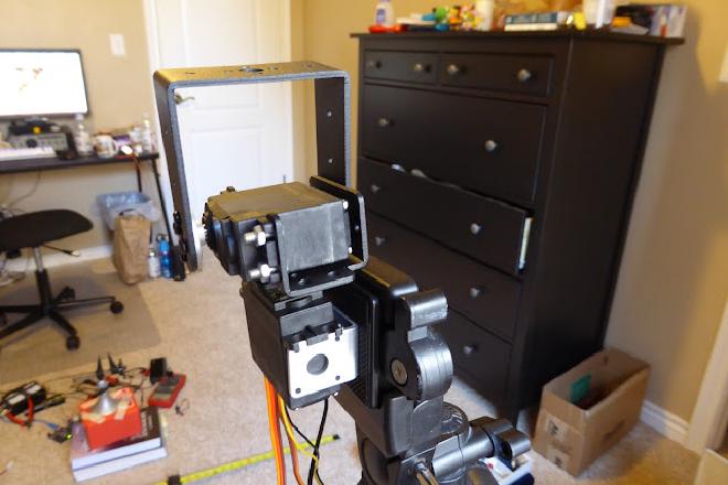
I also covered most of the wiring in wire loom to hide the mess. Then it was time for more zip ties! Simply zip tie everything to a tripod!
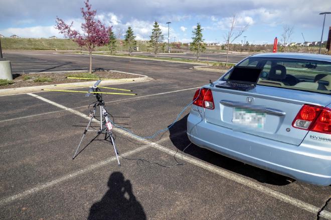
Now the setup is complete and basically portable. Time for field testing.
Field Test #
After waiting for the lightning and rain to stop, I picked a satellite that I knew was always transmitting (NOAA 18) and drove to an empty parking lot to test it out.
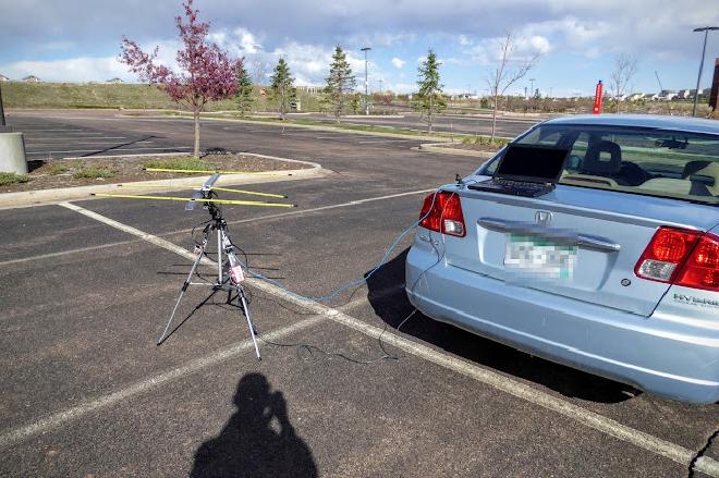

Here’s a video I took of it, sped up 40 times:
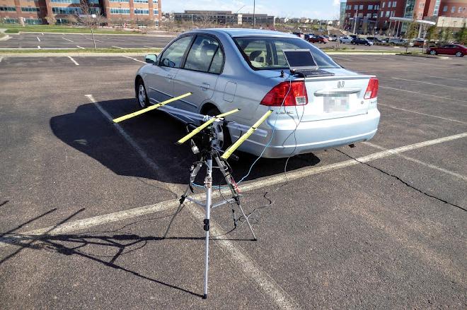
One problem I had was the Gpredict rotator control was only set to update when the antenna was 5 degrees off, so it didn’t update as often as I would have liked. Later, I set it to 1 degree. The wind also messes with the tape measure elements pretty badly, but I don’t think it was that big of a problem.
I tracked some of the XW-2 satellites after that, and they all showed up as well.
So, is it useful at all? Probably not. It is cool and I learned a lot, but actually driving somewhere, setting it up correctly (which involves reprogramming the arduino for every satellite), and then sitting around is pretty much the opposite of useful.
Most people want satellite trackers so that they can put them outside and then control the antenna from inside, which someone probably can’t do with mine unless they live in a really nice place (or build a radome). However, it could be useful for a small number of people who have covered balconies or porches. It wouldn’t receive the full effect of the weather and they wouldn’t be able to get more than 180 degrees from a balcony anyways.
Also, if you try to transmit the interference will kill the servos while you’re transmitting, so it’s useless for that (although that could probably be fixed).
Not counting things I already had (SDR, tripod, arduino, etc), the total comes for me came to around $60, which is almost $25, right? Really though, I think if someone wanted to build this project they could do it for around $25. Just buy the pre-made pan and tilt and zip tie an antenna to it.
Where will this project go next? I’m going to try to modify the azimuth servo to be full-rotation. I’m also planning on building another antenna for the 435 MHz region. Or maybe I’ll bin the whole thing and build a SatNOGS rotator.
Complete source code #
Comments: #
Hi, I’m Eleftherios from the SatNOGS team, we … #
elkos -
Hi, I’m Eleftherios from the SatNOGS team, we are glad you found our code useful and we are looking forward to join our community and see more stuff from you. :)
#### Hi, nice project. A compass module (+gyro) could b... [satman](https://www.blogger.com/profile/01419290676631576689 "noreply@blogger.com") -
Hi, nice project. A compass module (+gyro) could be an option instead for measuring the full rotation instead of a rotary encoder. Have you experienced any electromagnetic-noise because of your servos etc.? The good old aluminium foil could do a good option for shielding the servo otherewise. If your antenna has an azimut of 180 degree you could just tilt it over to the other side, that could solve your problem, but you would probably have a short signal loss.
How powerfull is the servo setup? Could it handle a 0.5 kg antenna?
Congrats on that nice project.
#### Hice job, congrats ! Exactly what I\`m looking for,... [Vic YO4TNV](https://www.blogger.com/profile/09495312386868679551 "noreply@blogger.com") -
Hice job, congrats ! Exactly what I`m looking for, linux, gpredict and arduino i will try to build it too . 73 de YO4TNV !
#### Thanks! I did think of using a compass, but not t... [Paul Schow](https://www.blogger.com/profile/02139879554145337777 "noreply@blogger.com") -
Thanks!
I did think of using a compass, but not to detect the rotation. I’ll have to look into that!
it doesn’t seem like noise is a problem, but shielding would probably be a good idea anyways.
I’m not sure exactly how much weight they can handle. I think balance is a big part of that too.
#### Great Article with components that can be acquired... [Chief Cook and Bottle Washer](https://www.blogger.com/profile/18311227368721846511 "noreply@blogger.com") -
Great Article with components that can be acquired in more remote areas of the world.
That said, I can’t see any images as your host, Blogspot, is blocked by many authoritarian governments as former countrymen use it as a platform for political protest.
So it’s off to Cambodia where almost everything is uncensored.
#### Hi again Today I came across this motor: http://ww... [satman](https://www.blogger.com/profile/01419290676631576689 "noreply@blogger.com") -
Hi again
Today I came across this motor: http://www.dx.com/p/40rpm-12v-encoder-motor-dc-turbo-worm-gear-motor-w-self-lock-434055?TC=USD&en20160526newarrivals#.V1b7eb7oSzk
I belive it could just fit your needs.
#### Can you track the signal strength, that is given y... [PhilCobbin](https://www.blogger.com/profile/00752686085586715309 "noreply@blogger.com") -
Can you track the signal strength, that is given you rotate about the satellite’s location can you measure the signal strength as a function of the tilt settings?
#### I haven't experimented with that at all, but i... [Paul Schow](https://www.blogger.com/profile/02139879554145337777 "noreply@blogger.com") -
I haven’t experimented with that at all, but it would probably be possible. Most of the drone antenna trackers (FPV) use a similar system.
#### Nice work :-) I actually did something similar t... [thazlett](https://www.blogger.com/profile/18187536925372319389 "noreply@blogger.com") -
Nice work :-)
I actually did something similar to this 3 years ago. I used the same pan tilt servo kit you appear to have used. As for code I only got as far as controlling the servos from the serial console (using WASD for control). After that I had other things going on and the project took a back seat. I have lost some of it now which is a shame.
Here are videos of my old rig which is now probably in my boxes of junk. I was testing the limits of those servos I think:
https://www.youtube.com/watch?v=OotKcJFz7SQ
https://www.youtube.com/watch?v=8Miy1syfaPk
I have recently been looking to pick it up again. What you have done here is exactly what I was aiming to do 3 years ago. I’m happy to see I wasn’t the only one who attempted it. 3 years ago I remember finding information on it quite difficult. I knew little about servos and it was also the first time I used an arduino. So it was a huge learning curve for me also. I also ran into that same issue with the panning servo.
This has sparked my interest once again :-)